
The basic architecture is a client/server one, using an Arduino as the client, and a standard Linux system as the server.
The Arduinos will not log data, they only get an instantaneous snapshot of the current status when they are quried – all the logging happens server-side.
Server
A Linux server hosts the “master” files –rrdcreate.sh, rrdgraph.php, rrdupdate.sh, and data.php. Initialise the rrdtool database with rrdcreate.sh, then schedule rrdupdate.sh and rrdgraph.php to run every minute via cron:
* * * * * cd Projects/sensors/; ./rrdupdate.sh > rrdupdate.log 2>&1 ; ./rrdgraph.sh >/dev/null 2>&1
These files can be found here
You’ll need to modify the scripts to account for the hostnames and the quantity of your sensors.
The RRD file is set up to handle up to five sensors – if you have more than this, then you’ll need to adjust the rrdcreate.sh script.
You will need to update rrdupdate.sh to pass in the hostnames for your sensors. I’ve added mine to DHCP/DNS so I know which is which by hostname alone. For example, the line sensor1=$(php data.php temp1) will call the data.php script with the “temp1” hostname, and query that. You shouldn’t need to edit the data.php script. If you have more than five sensors, extend this file too.
You will also need to update the rrdgraph.php file – this produces a number of graph images with well-defined names. You can write a quick HTML file around these if you want, but you will need to change some settings first:
- At the top, there are some time periods defined – extend or reduce as you wish.
- Change
$limitBarsto set any upper/lower boundaries to warn at. I’ve got mine set to 10C, 15C and 35C, and 20%, 40%, 70%, and 80% relative humidity, with hex colour codes defined too. - Change
$graphsto set the labels for each sensor - You might need to change the upper and lower temp limits in
$limitstoo, depending what your local weather patterns are like $dimensionsand$outputPathshould be fairly straight-forward.
Hardware components
The sensors themselves are made up of a number of items. At the core, is an Arduino Nano clone. I bought five from eBay for about £3.20 each. Communication is done via Ethernet – I’m using the WizNet W5100 – which I picked up five from eBay for £4.04 each. Finally, the sensor is the AM2320, which I picked up five from eBay for £1.22 each.
I also bought PoE to USB+Ethernet splitters for £5.99 each, and some 0.5m USB A->mini B cables, for £1.33 each, to save me from figuring out power at each location. I’m using an old PoE midspan to inject the power, and the PoE splitters pull the power off and provide power to the Arduino, and network to the WizNet module. Postage just happened to be free for everything.
You also need two 10K resistors per sensor, and probably a meter of wire per sensor if you use 10cm lengths like I did. It’s possible to make it smaller, but I found the Arduino ran a little warmer than I would have liked, so having the sensor further away will give a more accurate reading. I already had these, so I don’t have an approximate cost.
Altogether, it’s cost me £78.89 ~= £15.78/sensor
Assembly
Hook it all together! I recommend doing this on a breadboard first – I had a (real) ardunio kicking around which included header pins, so I just stuffed it into a breadboard. I soldered tails onto the pins of the WizNet module to make it more amenable to the breadboard.
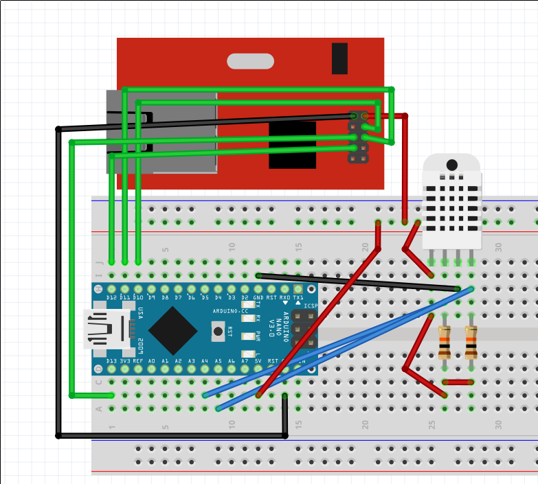
Wiring diagram
The Ethernet module connects directly pin-to-pin on the Arduino:
| WizNet W5100 Ethernet | Arduino Nano |
|---|---|
| +5 | +5V |
| GND | GND |
| NSS | D10 |
| MO | D11 |
| MI | D12 |
| SCK | D13 |
The sensor is a little more tricky due to two pull-up resistors needed:
| AM2320 Sensor | Arduino Nano |
|---|---|
| Pin 1 | +5V |
| Pin 2 | A4 (pull up to +5V via 10K resistor) |
| Pin 3 | GND |
| Pin 4 | A5 (pull up to +5V via 10K resistor) |
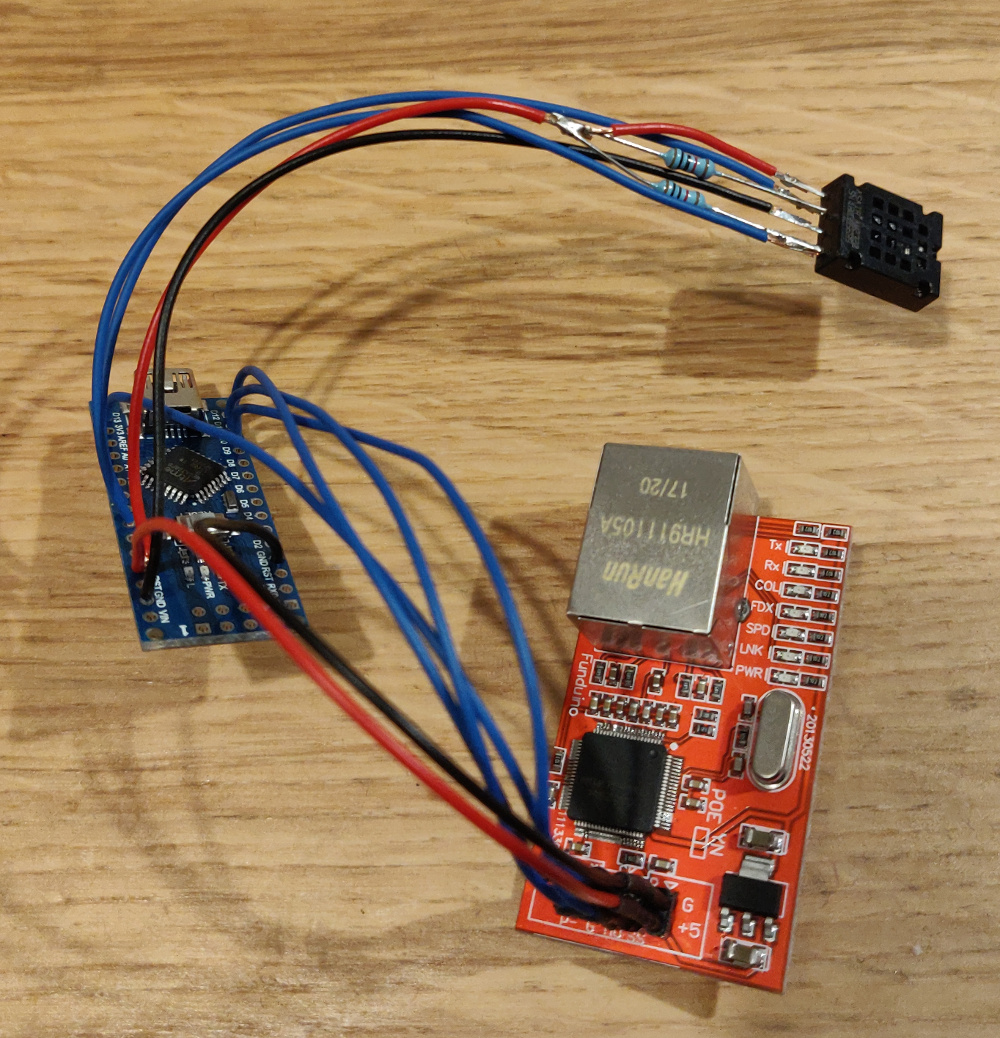
Finished product
Arduino Firmware
There’s Arduino libaries for the Ethernet module and the sensor. It should just be a simple case of pulling those in. In the Arduino Sketch, I’ve got a couple of constants for setting the MAC address of the Ethernet module, and a definition of a TCP port to listen on.
We simply initialise the Ethernet module, start a TCP server, and wait for a client connection. Then, we manually build a JSON file with the relevant data, send it down the TCP stream, and close the connection.
The Sketch can be found here